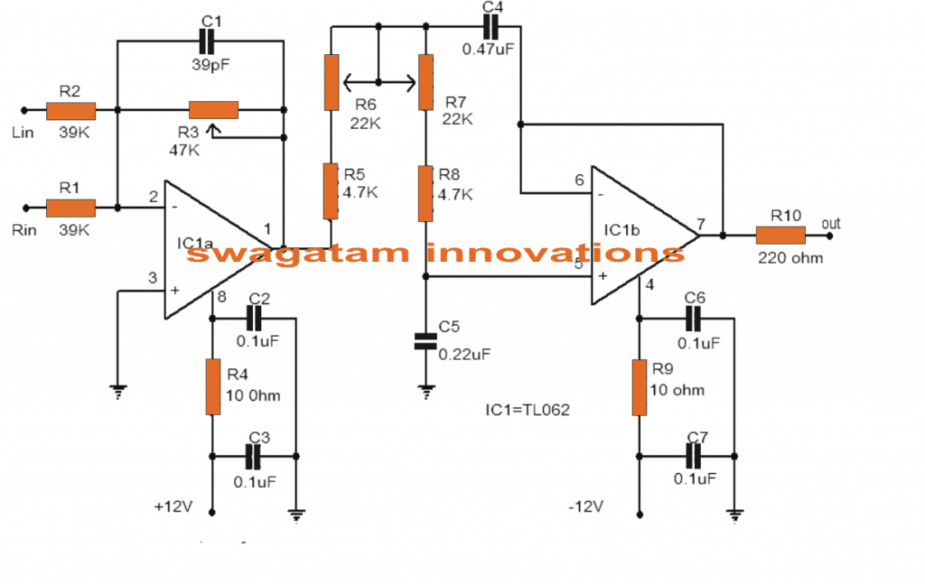
Wide Band Pass Filter Circuit Diagram

Wide band pass filter circuit diagram
Wide Band Pass Filter If the value of quality factor is less than ten, then the pass band is wide, which gives us the larger bandwidth. This band pass filter is called Wide Band Pass Filter. In this filter the high cut-off frequency must be greater than the lower cut-off frequency.
What is a band pass filter circuit?
A bandpass filter is an electronic device or circuit that allows signals between two specific frequencies to pass, but that discriminates against signals at other frequencies.
How does a band pass filter is constructed?
A simple passive Band Pass Filter can be made by cascading together a single Low Pass Filter with a High Pass Filter. The frequency range, in Hertz, between the lower and upper -3dB cut-off points of the RC combination is know as the filters “Bandwidth”.
How is wide band pass filter implemented?
WideBand pass filter BPF : The wide band filter has quite a lower Q factor. The BPF can be implemented using RC or LC, ie. using a resistor-capacitor for inductor-capacitor. The best is to use the Inductor capacitor filter as it has a low power loss.
Why is band pass filter used?
Band-pass filter functions are used where it is desired to transmit signals in a certain band of frequencies and block signals of lower and higher frequencies. This is what is done in “tuning” a desired frequency, such as a radio or television signal.
Why is it called bandpass filter?
band-pass filter, arrangement of electronic components that allows only those electric waves lying within a certain range, or band, of frequencies to pass and blocks all others.
What are the types of band pass filter?
A band-pass filter can be characterized by its Q factor. The Q-factor is the reciprocal of the fractional bandwidth. A high-Q filter will have a narrow passband and a low-Q filter will have a wide passband. These are respectively referred to as narrow-band and wide-band filters.
Is an RLC circuit a band pass filter?
An RLC circuit can be used as a band-pass filter, band-stop filter, low-pass filter or high-pass filter. The tuning application, for instance, is an example of band-pass filtering.
How is bandpass filter calculated?
Band Pass Filter using R, L and C Components The centre frequency of the band pass filter which is also termed as 'resonant peak' can be formulated by using the below equation: fc = 1/2π√(LC) Where L = inductance of an inductor whose units are in Henry (H).
What is a band pass circuit made of?
It is a combination of a high pass filter and a low pass filter. A filter that allows only the frequencies that are higher than it is called as high pass filter and the filter that allows the frequencies that are only lower than it is called as low pass filter.
What is the range of band pass filter?
Generally, the dielectric band-pass filters can be used over the frequency range from 300 MHz to 100 GHz. For high-frequency applications, NRD waveguide filters (Figure 7.38) gain interests because of the extremely low-loss and low dielectric constant materials that can be used in the design.
What is band pass frequency?
A passband is the range of frequencies or wavelengths that can pass through a filter. For example, a radio receiver contains a bandpass filter to select the frequency of the desired radio signal out of all the radio waves picked up by its antenna.
What is Q factor of a filter?
It is defined as the ratio of the initial energy stored in the resonator to the energy lost in one radian of the cycle of oscillation. Q factor is alternatively defined as the ratio of a resonator's centre frequency to its bandwidth when subject to an oscillating driving force.
What are the types of filters?
Four Major Types of Filters The four primary types of filters include the low-pass filter, the high-pass filter, the band-pass filter, and the notch filter (or the band-reject or band-stop filter).
What is the difference between wide band and narrow band pass filters?
Narrowband systems typically have lower data rate transmissions, whereas wideband systems support relatively higher data rate transmissions.
Is band pass filter active?
Active band pass filters (BPF) attenuate frequencies below and above a range of frequencies (i.e., the bandwidth or passband of the filter). Any signal with a frequency within that band pass range passes easily through the filter. Any frequency outside of the band pass is attenuated or reduced.
What is Q in bandpass filter?
The “Q” of a band pass filter is the ratio of the Resonant Frequency, ( ƒr ) to the Bandwidth, ( BW ) between the upper and lower -3dB frequencies and is given as: So for our simple example above, if the bandwidth (BW) is 400Hz, that is ƒH – ƒL, and the center resonant frequency, ƒr is 346Hz.
Is Butterworth filter bandpass?
The Butterworth and Chebyshev Type II filters have flat passbands and wide transition bands. The Chebyshev Type I and elliptic filters roll off faster but have passband ripple. The frequency input to the Chebyshev Type II design function sets the beginning of the stopband rather than the end of the passband.
Is bandpass the same as bandwidth?
Passband bandwidth is the difference between the upper and lower cutoff frequencies of, for example, a band-pass filter, a communication channel, or a signal spectrum. Baseband bandwidth applies to a low-pass filter or baseband signal; the bandwidth is equal to its upper cutoff frequency.
What is the opposite of bandpass filter?
In signal processing, a band-stop filter or band-rejection filter is a filter that passes most frequencies unaltered, but attenuates those in a specific range to very low levels. It is the opposite of a band-pass filter.
13 Wide band pass filter circuit diagram Images
46

Active Band Pass Filter Circuit Design and Applications Electronic

Active Band Pass Filter Circuit Filters Band Pass

an electronic circuit with two different types of voltages and the same

Low and High Pass Filter circuit High pass Circuit diagram Circuit

How to make transistor amplifier using 4 transostor electronics

Subwoofer Filter NE5532 Schematic PCB Subwoofer Subwoofer amplifier

Circuit Diagram Of Low Pass Filter Circuit diagram Circuit design

Projeto de um band pass para sub graves Caixa de som Eletrnica
Circuit projects Subwoofer Circuit diagram

High and Low Pass Filters Electronics circuit High pass Filters

15 Filter circuits using electronic coil ElecCircuitcom Basic
Post a Comment for "Wide Band Pass Filter Circuit Diagram"